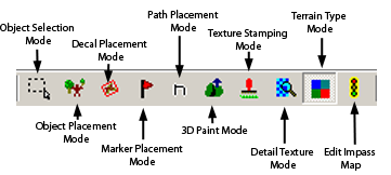
The Mission Editor has a set of buttons in a toolbar that can control various aspects of the ME. These buttons are separated into four different groups. The Cut & Paste buttons, allow you to edit your mission quickly and easily. The Undo, Redo buttons allow you to undo or redo any changes that you have done easily. The Modes buttons allow you to directly manipulate the mission that you are working on. Finally, the ErrorButtons are used for debugging your map.
Modes
Object Selection Mode
Object Selection mode allows you to select objects without fear of left clicking and accidently creating an object. It also includes a handy filter (that is also available in object placement mode) that allows you to determine what kind of objects will get selected when you drag select. Note that this is only a selection mode, and only for objects.
Object Placement Mode
As its name implies the Object Placement mode allows you to place on, move, and rotate certain things on your map. These things can be broadly separated into two categories:
Environment
Races
Each of these items has several tree branches. The Races category is separated into five groups: Chaos, Eldar, Guard, Orks, Space Marines. Each of these sub-categories is further separated into structures and troops.
The environment category is separated into 6 different categories: ambient_fx, gameplay, jungle, ork, single_player and urban. Each of these should be fairly self-explanatory. The most important of these is, of course, the gameplay category as it allows placement of starting positions, slag deposits, strategic points and other elements vital to Dawn of War gameplay.
To place an object on the world map, click on the selection you want from the tree and then left click on its desired location on your map. To delete an object, select it by ctrl-left clicking on it to select it (or alternatively left-click dragging it) and then press Del. Also, note that you can snap objects into place relative to the terrain or water surface. The radio button labeled Adjustable allows you to embed an object into the terrain, gives you a bit more freedom as it wont snap to the terrain right away. You can also place random objects from a tree branch by selecting that tree branch and left clicking as usual. For instance, if you wanted to place a random elder unit on the map you would select the Eldar->troops branch and then left click on a location on the map.
This mode also features the same type of filter as the object selection mode.
3D Paint Mode
The 3D Paint Mode is where you will be spending most of your time when you edit the terrain. It is a fairly simple tool that allows you to create a wide variety of terrain from mountains to small hills, to rivers. When in 3D Paint Mode you are presented with a brush in the Map Window (). This brush consists of two concentric circles; a white and gray one. The outer circle, the white one, represents the extent of the feather of the given brush (to be explained later). The inner circle, the gray one, represents the actual brush size.
While in 3D Paint Mode, the Heightmap edit Rollup is displayed in the Tool toolbar, and is composed of the following items:
Mode: The brush mode that you are in will determine which of the following options are available to you. Once you have the desired brush size and mode selected, simply left click and drag on the world map to create a line of terrain.
Additive : Adds terrain. Pressing the CAPS-LOCK key while in this mode will toggle the brush from additive to subtractive.
Subtractive : Removes terrain. Pressing the CAPS-LOCK key while in this mode will toggle the brush from subtractive to additive.
SetValue : Draws the terrain at a set value. This value is either a height preset or a setup height value. Pressing the CAPS-LOCK key while in this mode will toggle the brush from set value mode to smoothing mode. A useful feature in this mode is being able to sample the height of existing terrain. To do this, ctrl-left lick on terrain to select a terrain type, now anything you paint with the tool will be drawn at the selected height.
Smoothing : Smoothes out the terrain in a given area. Pressing the CAPS-LOCK key while in the mode will toggle the brush from smoothing mode to set value mode.
Brush Size : Modifies the actual size of the terrain that is going to be affected.
Feather : Feathers out the modification effect. That is a low feather value will create smoother terrain (either additive or subtractive), while a high feather value will create jagged edges. So for instance if you wanted to create a plateau you would choose a low feather value, on the other hand if you wanted to create a steep hill you would select a high feather value along with 75–80 strength value (see image).
Height : This modifies the height that the brush will paint at.
Height Presets : These are preset height values that are commonly used in mission building.
Strength : This determines the strength of the brush. Think of this as the amount of pressure that the brush applies to the terrain. Lower strength settings give finer control, especially for additive, subtractive and smoothing.
Decal Placement Mode
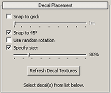
The Decal Placement Mode allows you to place Decals onto the terrain. Decals are basically textured objects of geometry that get applied directly on top of terrain. When decal placement mode is selected the toolbar window displays three separate roll ups:
Decals Placement: A list of decals available for you to use
Snap to grid: Determines if the item will be snapped to a grid, the grid size is determine by the value of the slider right below this checkbox.
Snap to 45: Snaps the decal to factor 45 degrees whenever it is rotated.
Use Random Rotation: When snap to 45 is turned on this will randomly generate a decal that is rotated by a factor of 45 degrees. Otherwise, this will create a decal that is rotated anywhere from 0 to 359 degrees.
Specify size: Allows you to specify by how much the decal will be scaled when it is first created. Note that scaling can later be adjusted by selecting the object and SHIFT-Right-clicking
Refresh Decal Textures: This will refresh the list of decals that you see. So for instance, if you have created a new decal to replace an existing one, or have updated a decal and wish to see the changes in the ME simply click the Refresh Decal Textures button, and the decal will be refreshed. Note that you need to restart the ME if you want to see any new decals that you have created and placed in the decal directory.
Decals: Provides you with a list of decals that are available for your use.
Preview: A preview window that allows you to see the decal before you add it/apply it.
Selection Information: If you have a set of decals selected, this contains information on those decals including their ID, position, Rotation and Scale.
When in Decal Placement Mode, the controls are as follows:
Left Mouse Button: Places a decal at the location of the cursor.
CTRL-LMB: Selects any decals under the cursor.
Right Mouse Button : Allows you to select a decal or drag-select decals.
SHIFT + LMB : Rotates the decal if you move the mouse.
SHIFT + RMB : Scales the decal. Moving the mouse will accomplish this.
Texture Stamping Mode
The Texture Stamping Mode is somewhat similar to the DecalPlacement Mode. Both serve the same purpose, to add details to the terrain. However, while you can delete decals off the terrain, you cannot do the same with textures. Basically, think of applying textures as painting onto the terrain. The only way that you can get rid of something that you have painted is to paint over it, or to reset the entire base terrain texture. Note that undoing the paint command does not work.
Texture stamping mode can be separated into three rollups.
Texture stamping
When in Texture stamping mode, the three options that appear are:
Spacing : This modifies that the textures will space apart when you are painting with a given texture. Painting in this case is defined as clicking and dragging the mouse on the world map. This creates several instances of a given texture.
Strength : This determines the strength of the brush. Think of this as the opacity of the current texture. A low strength texture is see-through, for example.
Color : This will modify the color of the given texture, but note that the original color of the texture is taken into account, so you will only get the color you picked when the texture itself is pure white, otherwise you will get a combination of your chosen color and the texture color.
Refresh Base Texture : This will reset the base texture to what it was before any type of paint was applied to it. You will be asked to confirm your choice before this command is executed.
Textures
List all the textures you have available to you to paint the terrain. Note that while all default textures included with the mission editor are plain color textures, textures with details can be used as well.
Preview
Provides a preview of the texture/color that will be used to paint the terrain along with the size of the brush (i.e. 4x4, 16x16, 32x32, etc.).
Detail Texture Mode
The Detail Texture Mode will allow you to modify the detail textures on the terrain or fill the terrain with a given detail texture. In other words, it overwrites existing terrain textures if applied on top of them. In Detail texture Mode, as usual, a preview and Detail Textures listing are available. Also available is the Refresh Detail Textures button that will work similarly to the Refresh Decal textures button.
Terrain Type Mode
Terrain Type Mode allows you to paint onto the terrain the characteristics of a given section of the map. Terrain type is used to determine which in game sounds and which effects are played when units walk over a certain part of the terrain as well which terrain is to be considered cover and what type of cover it is. When you select this mode a checkered grid pattern will appear over your map. In Terrain Type Edit rollup you will have three options:
Category: This is either Cover or Footfall and will determine what options appear in the terrain type drop down, as well as the type of overlay that will get displayed.
TerrainType : The options available in this drop down menu will depend on the category selected.
If Footfall is selected this drop down will contain:
Unknown
DirtSand
Rock
Grass
Water
If the Cover category is selected this dropdown will contain:
None
Light
Heavy
Negative
Blocking: Prevents buildings from being build on this terrain, however, units can still pass across the given terrain.
Stealth: Terrain that has stealth cover will imbue any units within it with the stealth/infiltrate ability.
Please note that both Stealth and Blocking mode arent fully implemented at this point in time.
BrushSize : The brush size that you will be painting with.
By default the map is of terrain type unknown which has the same value as the DirtSand terrain type, and the cover type is set to None.
Path Placement Mode
Path Placement Mode is used to modify or create animation paths for either camera, entity or squad movement. For each animation that you want to make for a camera, entity or squad, you will need to create an appropriate path. The camera animation that you are editing can be viewed and edited in this mode. Paths are mainly used for single-player maps. To move a point horizontally, simply move the pointer over the desired point, hold down the left mouse button, and then drag the desired point to the desired location. To adjust the vertical position of a point, move the pointer over the desired point, hold down one of the SHIFT keys as well as the right mouse button, and then drag the point to the desired height. Readjust horizontal position as necessary.
The Path placement mode is composed of the following four roll up menus, which are explained in more detail below:
Create
Select
Attributes
Keyframes
These are explained in more detail below.
Create
Allows you to create a path for either a camera, squad or entity. Note that not all path options are available for all these groups. Hence some of the possible options in Keyframes and attributes will not produce any changes in the path of the objects, even though they are enabled.
Select
The selection rollup allows you to select which of the paths you are editing, as well as allows you to rename and delete paths as needed.
The animation dropdown list allows you to select which animation in a set of given animations (camera/object) that you want to edit. There are also four checkboxes associated with these drop down menus:
Always display : The camera/object anim path will always be displayed if this box is checked, irrelevant of the current mode or whether the path is currently selected or not.
Show speed: If this box is checked parallel line following the path of the camera will appear above it. Speed is determined by the height of the speed line relative to the cameras path: the higher it goes, the faster the animation will move at that point.
3rd person: Shows the camera/moving object from a 3rd person point of view (your current camera view). When checked, the preview shows the cameras path from a 3rd person point of view. That is, the user can see the camera as a box moving along its path from a 3rd person perspective. When unchecked, the preview is shown to the user from the cameras perspective (ie. 1st person perspective) instead .
Pause Blend-out: Pause before blend out to previous camera view (before the animation started) occurs. When checked, it pauses the camera before a blend out. Click pl to finish the camera animation.
pl, pa, st: These are the play, pause and stop camera controls.
Anim Attributes
ID: Provides you with the ID of the currently selected anim.
Blend-in/Blend-out times: Allows you to edit the blend in and blend out times for the animation. Basically, this edits the time it takes for game camera to switch to animation camera or vice versa.
Keyframes are used to specify animation parameters and the values for these animation parameters are interpolated between keyframes. In order to smoothly interpolate these parameters, we use spline curves. KeyFrame Attributes and KeyFrame Operations are the tools that we use in the editor to achieve this.
Keyframe List Window
The Keyframe List Window allows you to view the keyframes in the currently selected animation. This window also lists the keyframes number, name (if there is one), length, and time. If you wish to modify multiple keyframes you can select them by using standard Windows methods like holding down the CTRL key and left clicking the selection or holding down the SHIFT key and dragging to select all choices between the starting point of the action and the cursor).
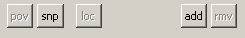
Keyframe Operations
pov(Camera only) : Moves the path camera location to the current Mission Editor camera location. This will effectively set the currently selected path point of the camera to be in the same location as the Map Window of the ME. In other words, you can set a bunch of camera keyframes, using this feature and when played back, keyframes will be at locations that you have indicated with the pov command.
snp (Camera only): This command can be toggled. When turned on it will snap the camera to the active camera viewpoint. loc: Sets the local rotation value at this keyframe, allowing the camera to look in directions other then along the path.
Add : Adds a keyframe right before the currently selected key frame. This Add function interpolates where the point should be and places it in between the two keyframes.
rmv (Remove) : Deletes currently selected keyframes.
Name : Allows you to set the name of a keyframe, if you wish.
X, Y, Z : Each sets the XYZ respectively coordinates for the location of the given keyframe.
The following functions are available only for editing move and camera animations:
Rotation : Allows you to set the rotation (in degrees) of a certain keyframe
Declination : Allows you to set the declination (up down rotation), also known as pitch. Note that for the camera negative values rotate the camera upwards. Positive values rotate the camera toward the ground.
Roll : Adjusts the roll of the camera.
Look Distance: Modifies the look distance of the camera. In other words, this distance is the distance that the camera will look at along the path. For example, imagine a camera looking at a point in front of it that moves along the camera path at the same speed. Generally we leave the distance to the point set at 1m, but you could have the camera look much farther ahead. Now, pretend that we made the distance to the point farther ahead. If the cameras path has a curve in it, the camera would start to turn well before it got to the curve, because its tracking the point moving ahead of it.
Shake Modifier: Modifies the amount of camera shake that occurs at this location on the path. Note that any changes that you make to this value will not be visible in the Mission Editor, youll need to start up the game and run it in order to see the effect of the Shake Camera Modifier.
Speed :Modifies the speed at which the camera moves through a given keyframe. This value can be between 0.01 and 100
Target Group : This drop-down list displays a list of groups on the map that can be the target of the camera.
Target Path : This drop-down list displays a list of path in that are located on the map and that can be used as a target (look at) path.
Target Keyframe :This option is disabled most of the time, unless you assign a target path to your camera, in which case you will be able to select the keyframe
Tension : Adjusts camera tension between the keyframes of the camera/object animations. Basically this means controlling the speed at which the camera moves through a keyframe. A positive value slows the camera down and a negative value speeds it up. A value of 0 causes the camera to move at a constant speed through a keyframe. For example, a high tension value (1.0) is often used for coming to a gradual stop.
Continuity : Adjusts the continuity between the keyframes of the camera/object animations. A negative value gives a sharper transition in the spline path at a keyframe and is also often used to replicate a sharp change in motion. On the other hand, a positive value gives a broader transition through a keyframe.
Bias : Adjusts the bias between the keyframes of the camera/object animations. This controls an item's lean to one side of the keyframe. In effect, the “slack” of the keyframe is moved from both sides of the keyframe to one or the other. A negative bias places the slack before the keyframe, and positive places it after.
Edit Impass Map
Allows you to edit where units can go or cannot go on your map. The Value drop box allows you to switch between passable, impassable and generated. This is usually used as a tool for fine-tuning the map. While you can break certain rules (i.e. make steep cliffs passable) using this feature it should not normally be used in that manner. The generated rules should take precedence. Editing the impass map is usually a last step process that is used when refining your map. Note that for environment objects, such as trees that you have added to the map or ruined buildings require the impass map to be edited in order to prevent units from passing through them.
Edit Terrain Properties
Edit Terrain Properties
The Edit Terrain Properties Window allows you to change several characteristics of your map. There are three major areas to this pop-up menu (including one textbox):
Lighting properties
Sunlight Color : Determines the sunlight color and displays its RGB values.
Shadow Color : Determines the shadow color to be used and displays its RGB values. Note that all of the red, green and blue components of the shadow color must be less then the sunlight color.
Time of Day : This determines the amount of light on the map, as well as the direction from which the light is coming from.
the bug with the stencil shadows occurs when you have the Time of Day set to 0, 50, 100. This is a bug/limitation with the shadow system, and those light angles will be disabled in a future version of the ME.
Sky
Sky Texture : A drop down menu allows you to choose one of several sky map textures.
Sky Scale : Changes the scale of the sky. This allows you to make the skybox bigger/smaller.
Fog
Fog Start Distance :: Determines how far from the camera the fog starts.
Fog End Distance : Determines how far from the camera the fog ends. Obviously fog end distance should be greater then for start distance. Typically the best results are achieved when the fog end distance is half the skybox difference.
Color: The RGB values for the fog can be adjusted from this drop down.
Misc
Detail Texture Repeat : Determines how many times the detail texture will be tiled in a given area. A higher value will provide more details, but with more repetition, while a lower value provides less detail.
Water
Water Set: A set of predefined water colors and sets.
Color: The color of the water. To change, simply click on the drop down and select a new color.
Alpha: Determines the alpha value (transparency of the water). The lower the value, the more transparent the water will be, the higher the value the more opaque the water will be.
Anim Speed: Determines the speed at which the ripples on the water are refreshed/drawn.
Repeat: Determines how many times the texture is repeated on the surface of the water. Basically, higher values of repeat create a sense of much smaller waves, on the other hand smaller values of repeat create a sense of much larger waves.
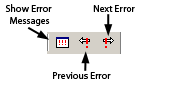
Error Buttons
Show Error Messages
A pop up window appears, displaying all the errors in the current map. If you select an error and then click Go To Error you will be taken to that error. Please note that there are some errors (such as missing attributes) that you cannot be taken to.
Go to Previous Error Location
Allows you to view the previous error in the list of errors.
Go to Next Error Location
Allows you to view the next error in the list of errors.